Calculating Pre-Heat according to BS EN 1011-2
Part 1 deals with the production and control of arc welding of metallic materials and is appropriate for all types of fabrication. It gives general guidance for the arc welding of metallic materials in all forms of product.
The BS EN 1011 series also contains the following titles:
- Part 2: Arc welding of ferritic steels
- Part 3: Arc welding of stainless steels
- Part 4: Arc welding of aluminium and aluminium alloys
- Part 5: Welding of clad steel
- Part 6: Laser beam welding
- Part 7: Electron beam welding
- Part 8: Welding of cast irons.
We are going to focus on 1011-2 and how this specification is used to calculate pre heat temperatures of ferritic steels.
Preheat for a welding process.
Preheating should be considered when there is a significant risk of hydrogen cracking in the welded joint.
Preheating is a process that is applied to increase the temperature of the work piece. According to BS EN ISO 13916:2017 section 3.1, the pre heat temperature should be measured ‘in the weld zone immediately prior to any welding operation’.
Why do we pre heat?
Preheating is carried out for the following reasons.
- It slows down the cooling rate of weld metal, HAZ (heat affected zone) and adjacent base metals, which yields a good microstructure to the metal, prevents martensite formation at microstructural level and prevents from cracking of the weld metal and HAZ.
- Preheating removes the diffusible Hydrogen from the base metal and hence prevents the chances of Hydrogen induced cracking (HIC).
- It helps in reducing the expansion and contraction rate of the metal.
- It Burns the unwanted material or impurities (if any) present on the joint surface.
- Preheating also helps in achieving better mechanical properties such as notch toughness.
How to apply pre heat
Pre heat can be applied using various methods, the 3 most common are:
- Propane Torch- Operators use a fuel gas and compressed air to apply flame directly to the metal component.
- Induction- Induction creates a magnetic subject that generates eddy currents inside the base metal, heating it internally from within. Induction accessories, such as cables or blankets, are positioned on the phase to generate the magnetic field.
- Resistance heating- Resistance heating uses electrically heated ceramic pads, placed on the base metal. The heated tiles transfer heat to the part through radiant heat and conductive heat where the pads are in contact with the part.
Point of measurement.
According to BS EN ISO 13916:2017 section 4.1, ‘The temperature measurement shall normally be made on the surface of the workpiece facing the welder, at a distance of A = 4 × t, but not more than 50 mm, from the longitudinal edge of the groove. This shall apply for workpieces thickness t not exceeding 50 mm in the weld’.
When the thickness exceeds 50 mm, the required temperature shall exist in the parent metal for minimum distance of 75mm or as otherwise agreed in any direction from the joint preparation. Where practicable, the temperature shall be measured on the face opposite to that being heated. Otherwise, the temperature shall be confirmed on the heated face at a time after removal of the heat source related to parent metal thickness to allow for temperature equalization.
Test equipment
Equipment used for temperature measurement should be specified in the welding procedure specifications, for example: —
- Temperature sensitive materials (e.g. crayons or paints)
- Contact thermometer (CT)
- Thermocouple (TE)
- Optical or electrical devices for contactless measurement (TB).
Calculating Pre heat.
When calculating pre heat there are 4 main essentials that should be taken into consideration. These are:
- Combined material thickness in mm.
- Heat Input measured in KJ/mm.
- Diffusible hydrogen content per ml/100g of deposited metal (Welding Consumables).
- Material CEV.
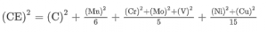
CEV- The carbon equivalent is a measure of the tendency of the weld to form martensite on cooling and to suffer brittle fracture. When the carbon equivalent is between 0.40 and 0.60 weld preheat may be necessary. When the carbon equivalent is above 0.60, preheat is necessary, post heat may also be necessary. The CEV is usually found on the material mill cert, however the precision of the CE value can be estimated by using the below equation:
Diffusible Hydrogen Content- Using table C.2, the operator must select a hydrogen scale for the consumables being used. As above, this is determined by identifying the diffusible hydrogen content of the consumable and should be stated by the consumable manufacturer in accordance with the relevant standard.
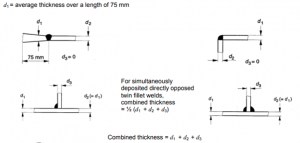
Combined Thickness- Next you must determine the combined thickness of the welded joint. Combined thickness is used to assess the heat sink of a joint for the purpose of determining the cooling rate.
For the same metal thickness, the preheating temperature is higher in a fillet weld than in a butt weld because the combined thickness, and therefore the heat sink, is greater.
If the thickness of the welded joint increases greatly beyond 75 mm from the weld line, it may be necessary to use a higher combined thickness value.
See the image below for guidance on calculating combined thickness.
Heat Input- BS EN ISO 1011-1
For many steels, abrupt cooling from the heat of welding should be avoided, this is due to the risk of hardening or cracking. For this reason, depending on the type of material, thickness of material and heat input, preheating and the maintenance of an upper or lower interpass temperature may be required, as listed in the relevant parts of EN 1011. The heat input shall be chosen, so as to be matched to the welding process.
The heat input during welding can be viewed as a main influencing factor on the properties of ferritic and ferritic-austenitic stainless steel welds in particular. This influences the time/temperature cycle occurring during welding.
Where appropriate, the heat input value may be calculated as follows:
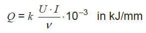
Where:
Q is the heat input.
k is the thermal efficiency.
U is the arc voltage, measured as near as possible to the arc, in V.
I is the welding current, in A
v is the travel speed in mm/s.
Once the data has been collected for the four main essentials (Combined material thickness in mm, Heat Input measured in KJ/mm, Diffusible hydrogen content, CEV) you should refer to Figures C.2 (a- m)- Conditions for welding steels with defined carbon equivalents.